
9. Image Menuadd chapter
9.1 Operations after Scanningadd section
Automatic Operations after Scanning is the first option that can be found in the Image menu. If activated, the operations within this menu point are performed automatically after scanning. Clicking any of the options once will activate the selected operation. Active operations are marked with a checkmark in front of the operation name. Clicking on an active option will disable it and remove the checkmark.
The operations listed below can be automatically performed after scanning; they are listed in the order in which they appear in the menu:
- Invert
- Mirror Horizontally
- Deskew
- Despeckle
- Black Border Removal
- Rotate Image 90 degrees (clockwise)
- Rotate Image 180 degrees
- Rotate Image -90 degrees (counter-clockwise)
9.2 Rotation Functionsadd section
![]() Rotate 90°
Rotate 90°
The image is turned to the right by 90 degrees.
![]() Rotate -90°
Rotate -90°
The image is turned to the left by 90 degrees.
Rotate: 180°
The image is turned upside down.
Rotate: 10°
The image is turned to the right by 10 degrees.
Rotate: -10°
The image is turned to the left by 10 degrees.
Rotate: 1°
The image is turned to the right by 1 degree.
Rotate: -1°
The image is turned to the left by 1 degree.
These functions can be undone by using the Restore Image option, the last option in the Image menu or Undo in the Edit menu.
9.3 Text Recognition Functions (optional)add section
BCS-2® allocates extensive text recognition functions. Prerequisite: BCS-2® OCR Module and the BCS-2® OCR Engine.
9.4 Image Informationadd section
9.4.1 Show image comment
With this function already existing comments to a single image can be displayed in a pop-up window.
9.4.2 Show Tiff Tags
If images of the format TIFF are included in a scan order, the TIFF Tags which were either committed by the scanner or defined before the import into BCS-2® are displayed in a pop-up window. TIFF Tags defined and edited in BCS-2® are written during the transfer of images and can therefore not be displayed beforehand.
9.4.3 Information about current image
Special image information can be retrieved via this function:
- Width in pixel
- Height in pixel
- Color-Depth (bits per pixel)
- Resolution (dpi)
- File format (e.g. TIFF, JPEG; PNG)
- Compression (e.g. CCITT GROUP4)
- Size (in bytes)
- Size (KB)
9.5 Image processing functionsadd section
The Image menu offers special functions to conveniently increase the quality of scanned images.
![]() Grayscale
Grayscale
This function has no effect on the image file. It will however greatly improve the display quality of the image by softening hard contrast edges with gray tones. The quality may be reduced at very high zoom levels. (Hotkey: F8)
![]() Despeckle
Despeckle
Small points (Impurities) on the image are automatically removed. It is recommended you use this function only on bitonal (black and white, 1 bit per pixel) images. (Hotkey: F6)
![]() Deskew
Deskew
The image is automatically properly aligned. (Hotkey: F7)
9.5.1 Further Image Operations
Invert
Image colors are inverted. (Hotkey: SHIFT+F6)
Flip Horizontally
The image is flipped horizontally.
Flip Vertically
The image is flipped vertically.
![]() Whiten Black Borders
Whiten Black Borders
Whiten the black border surrounding a scanned image.
The menu point Restore Image in the Image menu will undo any of these functions. The function corresponds to the Undo point in the Edit menu, and can also be performed by pressing the CTRL+Z key combination.
9.5.1.1 Configure Black Border Removal…
The settings for the black border removal can be configured here. Best results are attained with bitonal images.
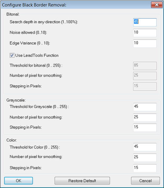
When using the black border removal tool on bitonal images, you have the choice of using either the LeadTools function or an alternative algorithm. To use the LeadTools function, the use LeadTools Function option must be checked. Using the LeadTools function will lead to better results for most images.
Following parameters can be defined for the LeadTools function:
Search depth in any direction
Admissible values are 1…100. The value determines the percentage within the image dimension (top to bottom, bottom to top, left to right, right to left) in which the search for the threshold between black and white takes place. The default value is 45%, meaning that a search for borders from every direction takes place in 45% of the image.
Noise allowed
This parameter defines how much noise is allowed. Admissible values are 1 through 10, the default value being 10, meaning noise is allowed.
Edge Variance
This parameter defines the variance permissible in the form of the edge. Admissible values are 1 through 10, the default value being 10, meaning a large variance is allowed.
Following parameters can be defined for the internal function:
Threshold for bitonal/Grayscale/Color
Brightness-values between 0 (black) and 255 (white) from which the algorithm defines the threshold for the transition to white.
Number of pixel for smoothing
This value defines the number of average pixels for checking the threshold.
Stepping in Pixels
This number defines the accuracy of the analysis: for example, a value of 10 means a test is performed every 10 rows. The ascertained value is then applied to that row as well as the nine rows before it.
9.6 ICC Profileadd section
With the help of an ICC profile the color space of color – input – devices and color – output – devices, e.g. scanner, monitor, etc. can be described with normed data formats, so that this color profile can be interpreted by other color-output-devices and the reproduction is as similar as possible.
With BCS-2® it is possible to obtain, delete and save committed color profiles for other post processing programs, furthermore BCS-2® can attach saved color profiles to images.
9.7 Page Splitting and Maskingadd section
9.7.1 Manual Page Splitting
With the manual page splitting it is possible to subsequently separate images.
The mode is activated by selecting the Toggle Manual Page Splitting option in the context menu (right-click) or via Page Splitting and Masking → Toggle Manual Page Splitting in the Image menu.
For quick access use the F11 key or the appropriate button in the Tool Bar:
![]()
In the page splitting mode a red splitting-line can be moved over the image. To move the splitting-line to the left or right, move the mouse cursor over the red line. The cursor will change into a double headed arrow; you can now move the splitting line by holding the left mouse button. The line can also be moved by using the arrow keys.
Selecting the Split Page/Apply Mask option will trigger the execution of the page splitting at the predefined position. The old image is discarded and two new images are created: the left and right side. After the splitting-line has been positioned, the page separation can also be triggered by pressing the ENTER key.
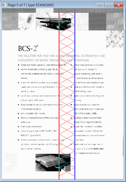
If needed the middle section of the original image can be cut out (for example to remove the shadow of a book crease). For this purpose an inner margin can be set. This function is accessible via the option Toggle Manual Page Splitting with Inner Margin (normal) in the Image menu under Page splitting and masking or via the context menu. The red line is the border of the left side; the right border is visible as a blue line, both movable with the mouse cursor. The red area in between the two lines (see screenshot) will be discarded when the function is performed.
When page splitting is performed (by pressing the Enter key), the image will be split into the part from the left image border to the splitting line (red), and from the splitting line (blue) to the right image border.
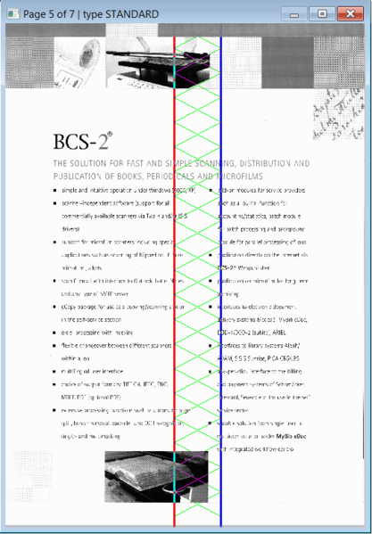
It is also possible to separate images with an overlapping inner margin, allowing you to maintain parts of the other page; this is very useful if the submittal being scanned is tightly bound and the normal page separation would lead to the loss of information. Select the Toggle Manual Page Splitting with Inner Margin (overlapping) in the Image menu or via the context menu. In contrast to the “normal” inner margin the red line is the border of the right side, the left border is the blue line, the green area in between the lines will a. When page splitting is executed, the image will be split into the part from the left image border to the splitting line (blue) and from the splitting line (red) to the right border.
Exit the page splitting mode by pressing the R button, thereby removing the page-splitting line.
9.7.2 Mask Mode
In the mask mode, an area of an image is defined that will become the new image after the mask is applied. The basic idea is to always obtain the same area of an image when scanning a large number of documents, for example microfiches. Page splitting can be performed simultaneously if desired.
The mask mode is started by selecting the Toggle Mask option in the Image under Page splitting and masking menu or the context menu.
To use the mask and page splitting simultaneously, select the option Toggle Mask with Splitting Line. If you also wish to remove the middle section select the Toggle Mask with Inner Margin (normal) option, if you wish to maintain a part of each side on the other page select Toggle Mask with Inner Margin (overlapping).
To change the size of the mask, position the mouse cursor on a line of the mask you wish to resize and drag into the desired size and shape by holding the left mouse button. If you position the mouse curser within the mask it is possible to move the entire mask by clicking and holding the left mouse button. After the operation was performed by selecting the Split Page/Apply Mask option or pressing the Enter key, the image will be replaced by the content of the mask. If a page-splitting line was also active (Toggle Mask with Splitting Line), the content of the mask will additionally be split into the defined two parts.
9.8 Multi Maskingadd section
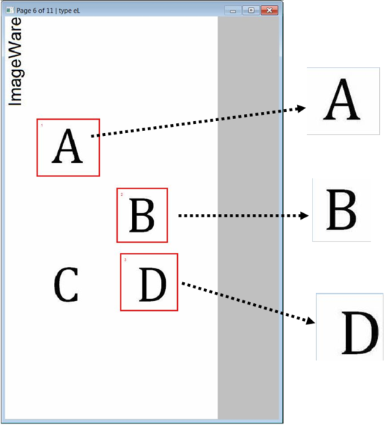
BCS-2® also offers the possibility of simultaneously defining multiple rectangular masks for a certain scan format (format, color depth, orientation) in an image. These tiles (sections from the original image) can be transformed into new images or have their content replaced with the contents of another mask, thereby making for example the manual thumb removal possible.
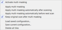
This function can be accessed by selecting the option Multi-Masking — Activate Multi-Masking in the Image menu, or alternatively by simply selecting Activate Multi-Masking in the Edit Image Shortcut context menu.
When Mulit-Masking is active the Edit Image context menu (right click in the image) will only display the mulit-masking functions.
9.8.1 Multi-Masking Procedure
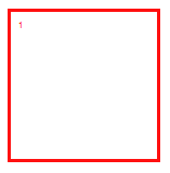
When Multi-Masking is active, multiple mouse-movable masks (tiles) can be created by selecting a section and “pulling” it with the mouse. The individual tiles are numbered.
Context Menu Edit Image
- After all masks have been placed as desired, you can perform the Multi-Masking function by pressing the ENTER key or selecting the Apply Multi-Masking menu point. Each mask will then be transformed into a new image and the original image is discarded when Keep Original Scan after Multi-Masking is deactivated. The new images are inserted into the order after and in place of the old image, their sequence corresponds to the numbers of the tiles.
- Additionally you can differentiate between the Apply Multi-Masking Automatically after Scanning and Apply Multi-Masking Automatically before Next Scan functions.
- The option Keep Original Scan after Multi-Masking will allow you to keep the original image. The newly generated images will then be inserted into the current order behind the original image. This option is activated by default when you launch Multi-masking for the first time.
- You can also save your Multi-Masking configuration via the option Save Current Configuration… or Load Saved Configuration….
- The menu point Delete All Tiles will make BCS-2® delete all tiles and their corresponding positions.
9.8.2 Multi-Masking Details
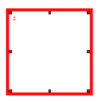
The individual tiles can be edited and moved after having been created by “pulling”. To do so left click on the tile you wish to edit, this will highlight the frame of the selected mask.
To change the size of the mask, position the mouse cursor on a line of the mask you wish to resize and “pull” into the desired size and shape by holding the left mouse button.
By clicking and holding the left mouse button within a mask-tile it is possible to move the entire mask.
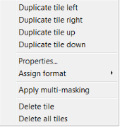
A right click on a selected tile will open a special context menu with following options and functions:
- Duplicate tile left/right/up/down: A selected tile can be duplicated to the right or left and up and down as long as sufficient space is available in the chosen direction of the image. An identical tile will be created bordering the selected tile in the chosen direction. This function can be performed consecutively in different directions.
- The option Assign format defines a fix standard format (A3, A4, A5 oder A6) for the selected tile.
- Individual tiles can be deleted by clicking the Delete tile option. The numeration of the tiles will change accordingly.
- Performing the Multi-Masking operation is also possible here (Apply Multi-Masking).
- Selecting the Properties… menu point will open the dialog window in which the Tile Properties can be defined.
9.8.3 Tile Properties
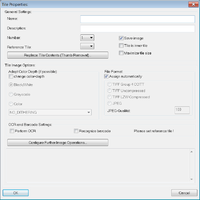
Among other properties, the Name and Description of a tile can be defined here. Also, the Number of any given tile can be edited, giving you control over the sequence of the tiles.
A Reference Tile can be set, which will replace the contents of selected tiles with the contents of the reference tile.
Note: For both the reference tile and the tile you wish to replace, the property Tile is inner tile must be activated. Additionally the check-box Save image must be deactivated.
You can also select which other operations are to be performed when the Multi-Masking function is applyed:
- Adapt Color Depth: If the image being edited is in color, the tile can be saved in bitonal or gray scale (gray scale images can be saved as bitonal tiles). The color diffusion algorithm can be defined as needed.
- By default the file format is “automatically assigned”. If desired the file format can be manually defined in the File Format area, after the option Assign automatically was deactivated.
- Activate the Perform OCR and/or Recognize barcode option to activate the text- and/or barcode recognition within the tile.
- Press the Configure Further Image Operations button to open the context menu Image Process Settings in which you can select and define the sequence of further image operations, such as deskew, despeckle, black-border-removal, etc.
9.8.4 Thumb Removal via Multi-Masking
With BCS-2® it is also (optionally) possible, to automatically remove thumbs that typically appear when using overhead scanners without a glass plate. The three Thumb Removal steps:
- Start a new order and create a scan on which the thumbs (right and left) appear.
- Activate Multi-Masking. The quickest way is by clicking the appropriate button in the tool bar or in the imagetools.
- Define two tiles. One tile encasing the thumb (left) and the second without a thumb (the contents of the second tile will replace the contents of the first tile).
- Next, activate the first tile (tile 1) with a left click. Now right click on tile 1 to access the selected tile context menu. In the Properties… window do the following:
- Set tile 2 as the reference tile.
- Check the Save image box.
- Check the Tile is an inner tile box.
- Now click the button Replace Tile Contents (Thumb Removal)…. Activate the Activate Thumb Removal option and the Use contents of reference tile for filling option in the appearing dialog window.
- Now activate tile 2 with a left click and uncheck Save image in the Properties… menu of this tile
9.9 Imagetoolsadd section
The BCS-2® Imagetools offer various image processing functions for scanned documents. The image tools can be accessed either by selecting the Show Imagetools option in the Image menu or clicking the Show Imagetools option in the Image Edit Context Menu. Selecting this menu point again or clicking the X in the title bar of the Imagetools will once again hide the Imagetools.
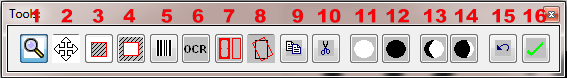
Button Functions (from left to right):
- Zooms in on selected position
- Moves the image within the window
- Erases around selected area
- Erases within the selected area
- Recognizes a barcode within selected area
- Performs text recognition in the selected area
- Toggles Multi-Masking function
- Copies selected area to the clipboard
- Cuts out selected area and moves it to clipboard
- Increases brightness
- Decreases brightness
- Decreases contrast
- Increases contrast
- Undoes last action
- Applies changes
The Imagetools can also be displayed horizontally by selecting the corresponding menu point in the Image menu.
9.10 ImageSuiteadd section
With the ImageSuite scans can be automatically cropped and aligned, the BCS-2® ImageSuite is required for this function.